Mesh Generation for HGS Models using AlgoMesh
We are pleased to announce that all new builds of HydroGeoSphere support 2D finite element meshes exported from AlgoMesh in the .AH2 format. The following is a guest post describing how to create and export a 2D mesh with AlgoMesh.
Mesh Generation for HGS Models using AlgoMesh
By: Damian Merrick of HydroAlgorithmics
High-quality finite element mesh generation is an important part of building a HydroGeoSphere model. Modelers must balance creating mesh elements small enough to accurately represent the physical phenomena being modeled with the need to minimize overall node count to avoid long simulation run times. The shape of elements is also important, as an abundance of thin triangles with angles in excess of 90 degrees can cause numerical instability and lengthen run times. Mesh generation must also take into account important model features, such as rivers, lakes, wells, springs and faults, to ensure that these are modelled with sufficient accuracy.
AlgoMesh
This blog post explores the use of a new software tool called AlgoMesh for building HGS model meshes. AlgoMesh is a powerful automated mesh generator from HydroAlgorithmics that utilizes a combination of advanced geometric algorithms to produce high-quality two-dimensional triangular meshes. It has a graphical user interface allowing interchange of input geometry and generated meshes with GIS software, manipulation and resampling of input geometry, and comprehensive control over element sizing. AlgoMesh allows exporting 2D mesh geometry in the .AH2 format for use in HGS models using the “read algomesh 2d grid” grok command.
Bringing In Model Geometry
To illustrate the use of AlgoMesh with HGS, we will build a mesh for a watershed model. We start with two shapefiles: one delineating the boundary of the watershed and another the major streamlines within.

Model Geometry
The first step is to create a bounding box outside the watershed’s boundary polygon. We note down the minimum and maximum coordinates of the watershed boundary, and buffer these out from the boundary slightly to produce a rectangular bounding region outside the model extents. We enter the four corner coordinates of this bounding rectangle in a simple comma-delimited X,Y text file and open this in AlgoMesh:
232750,285450

235500,285450

235500,281000

232750,281000
We could alternatively have created a rectangle around the boundary region in GIS software and imported it into AlgoMesh from a shapefile.

Setting up the outer boundary in AlgoMesh
Once we have a bounding rectangle in AlgoMesh, we import our watershed boundary shapefile as a “Spline set”. Spline sets are collections of polylines or polygons that form a feature or boundary of the model. AlgoMesh allows each polyline or polygon to be sampled linearly – as you would normally expect in GIS software, for example – or as a cubic spline curve, and offers various parameters for controlling the spacing of finite element nodes along them.
Here, we will bring in the boundary polygon as a linear polygon. The point spacing along the original polygon is somewhat irregular, with some points close together and others farther apart. For our model, we would like to produce elements of relatively uniform size along the boundaries, so we tell AlgoMesh to resample the polygon at 50 meter intervals.

Setting up spline properties
We then tell AlgoMesh to add this spline set directly into our mesh to form the outer boundary of the model. AlgoMesh produces an initial Delaunay triangulation of the model – both inside and outside the boundary polygon. We select one of the triangles outside the polygon and press the “-” key to tell the software that this area is outside the model extents, and the outside area turns a light gray color to show this. We now have a uniformly-sampled outer boundary for our mesh.
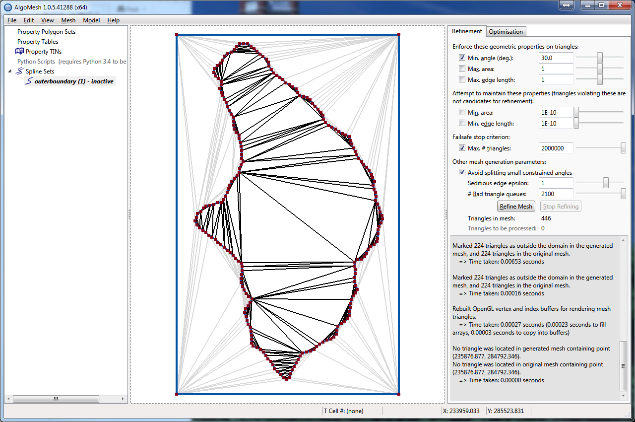
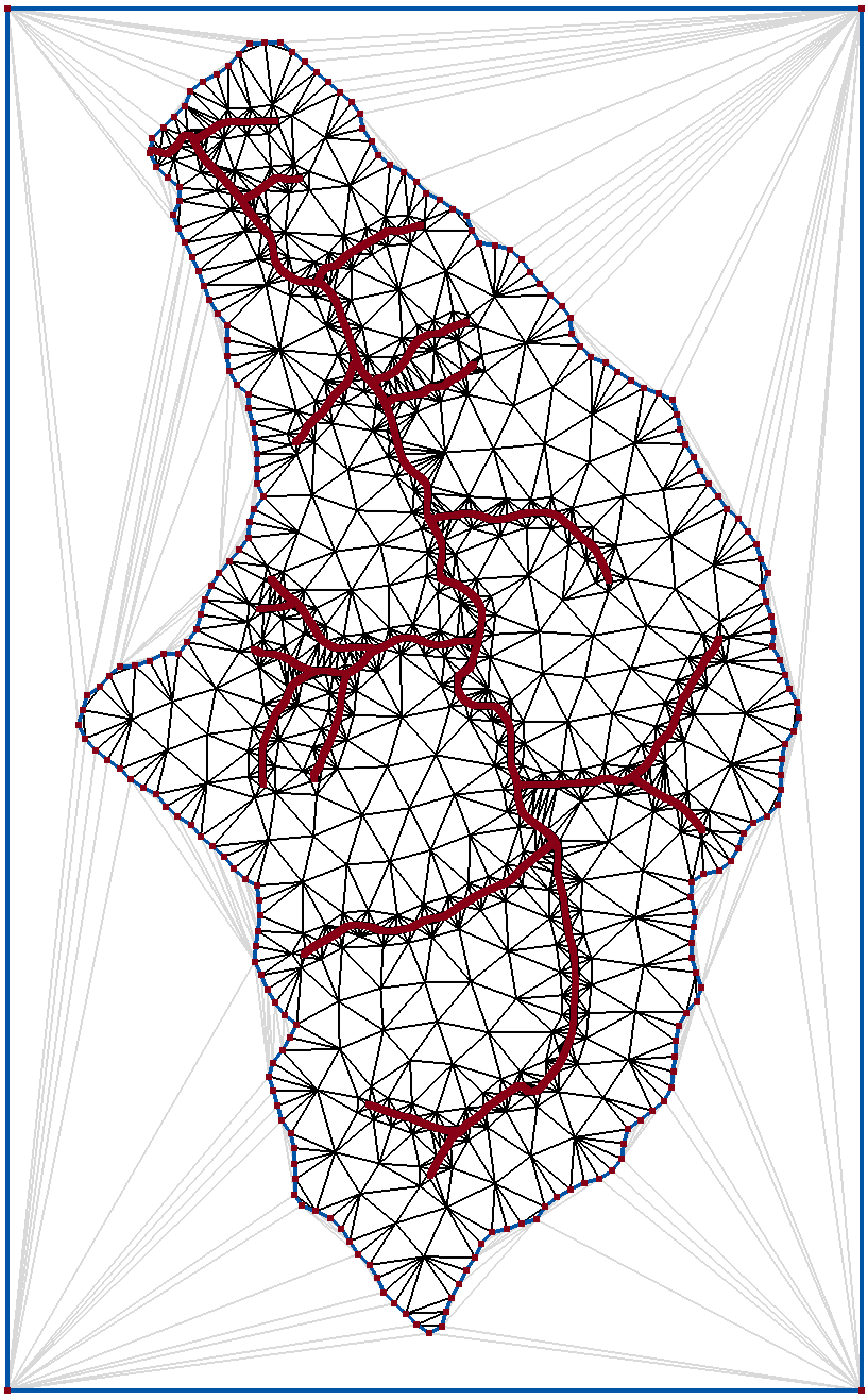
Specifying the inner portion of the model domain
Note that the triangulation produced here is not a proper mesh for the model – it simply joins up the points that have been added so far. Soon, we will run the mesh generation process to produce a quality finite element mesh based on our geometry. The light-gray triangles outside the model extents will not be included in the mesh generation process or our final geometry.
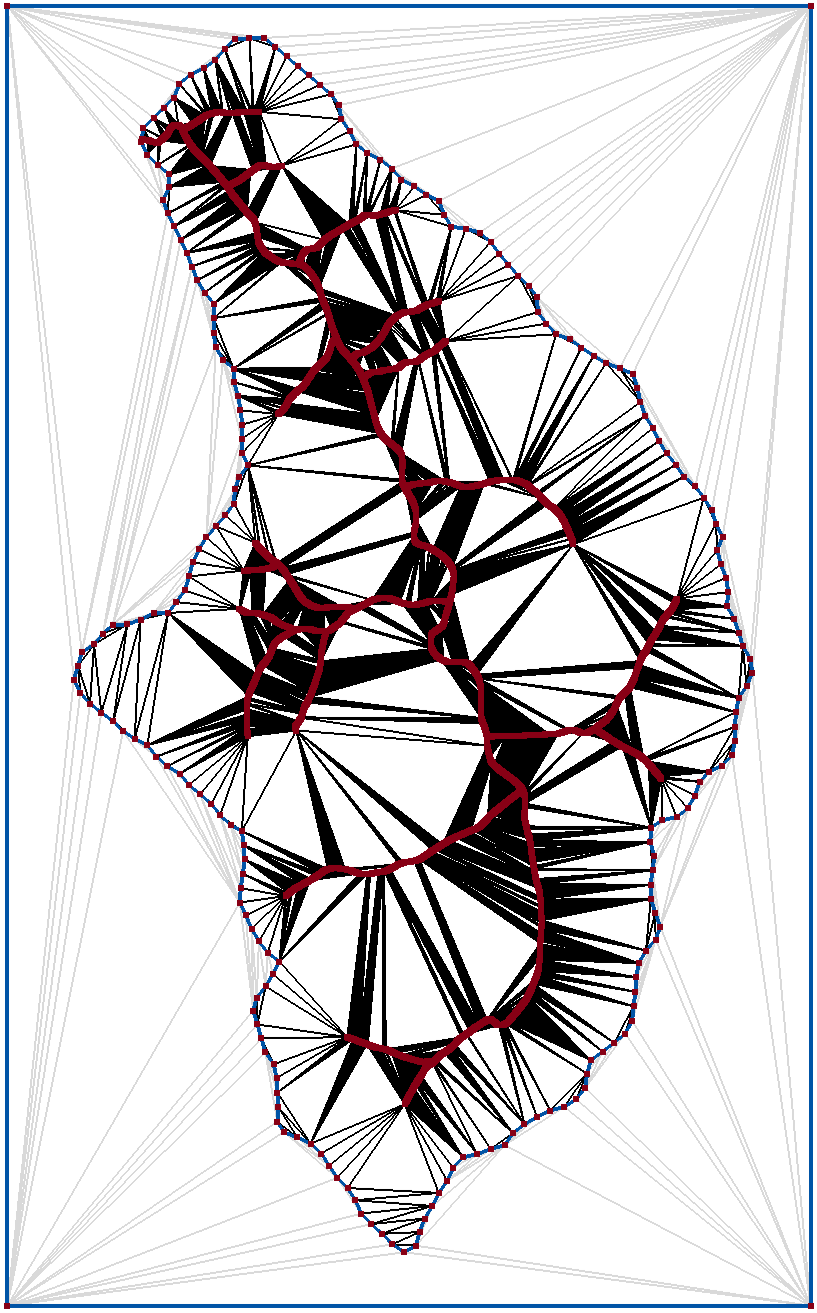
Before we run the mesh generator, we have to add our streamlines. We do this using a similar technique to adding the boundary. We first import the streamlines shapefile as a spline set. For our model, we want nodes along these streamlines to be no more than 1 meter apart, so we tell AlgoMesh to resample appropriately.

Defining streamlines
Since the streamlines lie fully inside our existing model domain, we don’t need to explicitly tell the software to add these to the triangulation. Instead, we leave them as an active spline set, which will be added automatically to the mesh when the mesh generation process is started. If we produce a mesh initially and then decide that the sampling interval between nodes needs to change, we can rapidly return to the sampling settings, adjust the interval, and restart the meshing process without reimporting the geometry.
Generating the Mesh
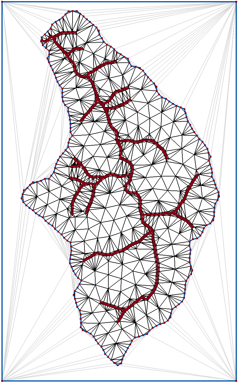
We are now ready to start the mesh generation process. AlgoMesh includes two different algorithms for generating meshes: refinement and optimization. The refinement approach is a very fast algorithm that generates reasonable, but not great, meshes. It is a similar algorithm to that of the popular software “Triangle” used in many other user interfaces for finite element meshing. The optimization approach is a multi-level variational algorithm which is slower than refinement, but which tends to produce elements of much higher quality.
One characteristic of the optimization approach is that it tends to produce high-quality triangles (with close to 60 degree angles) in most areas, but does not provide any strict guarantee on the angles, and may sometimes produce a small number of thinner triangles near boundaries. The refinement approach, on the other hand, does not do as well in global element quality, but can guarantee a desired minimum angle of up to around 30 degrees. To get the best results in AlgoMesh, we make use of both approaches: we generate the mesh first using the optimization approach, and then apply the refinement approach afterwards, to eliminate any “bad” triangles that were produced.
The optimization approach offers many settings to customize the mesh generation process, but the default values of these are usually quite reasonable. For our purposes, we change just three settings. The first is the “distance (grading) factor”, which we change from the default of 0.4 to 0.7. This number defines how rapidly element size changes between the elements at the boundaries and linear features in the model (the outer boundary and the streamlines, in our case), and the open areas of the model. The higher value of 0.7 here produces a somewhat more rapid grading in element size, reducing the number of nodes in the mesh compared to the default. A lower value would produce a much smoother grading between small and large elements, but would result in a higher node count in the final mesh.

Parametrising the optimisation
The second setting we change is to enable a global maximum edge length of 80 meters. This constrains the maximum node-to-node length in the final mesh, which will put an upper limit on the element size in the open areas of our model.
Thirdly, we set a “quality preset” for the optimization process of “6. High”. This configures the mesh generator to produce the highest quality mesh. Lower values here would produce a mesh with a somewhat higher node count and possibly more elements of poorer quality, but would speed up the mesh generation process considerably. Changing this setting allows a trade-off between the time taken to generate the mesh and the resulting mesh quality.
We start the optimization, and AlgoMesh gradually adds more nodes, smoothing the mesh as it proceeds, until it reaches completion. We then run the refinement process with a 20 degree minimum angle to produce the final mesh.
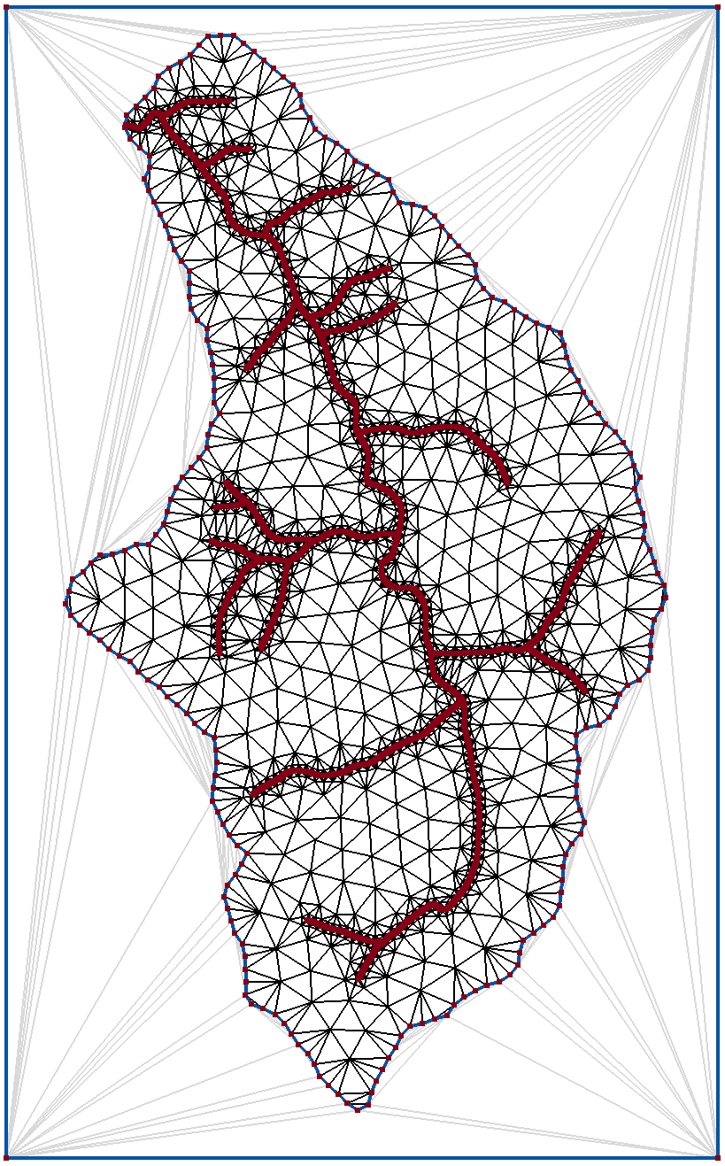
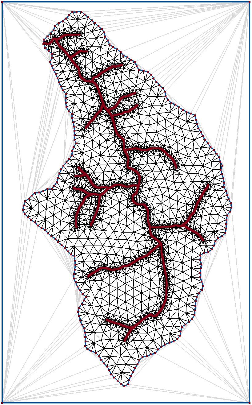

Finally, we export the mesh from AlgoMesh in .AH2 format, ready to be imported in an HGS model.

Final 2D Mesh
For more information on AlgoMesh contact Damian Merrick: info@hydroalgorithmics.com